Cleaning “No-Clean” Flux for Maximum PCBA Reliability
No-clean flux is a type of soldering flux used in electronics assembly that leaves behind minimal-to-no residue after the soldering process. Flux is a material applied to surfaces before soldering to facilitate the formation of strong and reliable solder joints. No-clean flux is designed to eliminate the need for post-solder cleaning, as any residue it leaves behind is typically non-corrosive and doesn't negatively impact the performance or longevity of the electronic components. This simplifies the manufacturing process, saves time, and reduces the risk of damaging sensitive components during cleaning.
One common misconception is that no-clean flux can be safely and reliably left on the finished circuit board assembly under all conditions. However, case studies document that the presence of no-clean flux has caused intermittent faults and failures during normal operation of the PCBA.
For a no-clean flux to pose no risks, the manufacturer must actively remove it or render it benign. Therefore, the critical issue at hand explores transforming no-clean flux into a benign state and understanding the consequences if it is not. This is particularly important as reliability becomes more critical, as is often the case for aerospace and medical device electronics.
Electrochemical Migration (ECM) and Dendritic Growth
Around 70% - 80% of electronic assemblies are currently constructed using a no-clean process [1]. With the introduction of no-clean flux, flux residues are considered harmless, and the practice of cleaning electronics has long gone. This reduces the need for wastewater and reduces the cost of waste solvent treatment while increasing process throughput.
While the cost reduction attribute attracts electronics manufacturers, the failure analysis of the returned parts somewhat neutralize this advantage. The presence of no-clean flux has caused problems like Electrochemical Migration (ECM), dendritic growth, and corrosion [2].
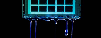
Electrochemical migration is a phenomenon that occurs in electronic circuits and components where unintended metal migration takes place across insulating materials due to the presence of voltage, humidity, and ionic contamination. It involves the transport of metal ions from one electrode to another through an insulating material, often resulting in the formation of conductive paths, called “dendrites” that can lead to short circuits or other malfunctions.
This phenomenon is driven by the migration of metal ions under the influence of an electric field, aided by moisture or humidity that facilitates ion movement. Common sources of ionic contamination include residues from manufacturing processes, such as flux residues or contaminants left on the circuit board.
Undried No-Clean Flux Under Components
To support thinner product profiles, electronics manufacturers have opted for packages like QFN and LGA because of their low standoff heights (0.5 – 2.5 mils). To render the no-clean flux under these components harmless, it is the job of process engineers to process the flux into its benign state. In technical terms, it is called benign glassy state (BGS) [1].
Exposing flux residue to the heat of reflow soldering removes flux volatiles via venting spaces. In addition, the activators in the flux are encapsulated by non-polar resin thus eliminating any reliability concerns. However, in situations with poor venting spaces, it is difficult for the flux residue to reach its benign state beneath low standoff components.
The entrapped solvent can keep the flux residue in a liquid state, and then the activators can contribute to corrosion under humid conditions. Figure 1 summarizes this process. Figure 2 shows entrapped wet flux under an 11-month-old QFN component.
In another scenario, manufacturers prefer to assemble components and electromagnetic shields simultaneously [3]. The electromagnetic shield may have few-to-no venting holes which would allow flux fumes, solvents, and activators to escape during reflow soldering. Figure 3 depicts the consequences. Consequently, sensitive circuits like batteries, RF displays, and LEDs will undergo intermittent failures.
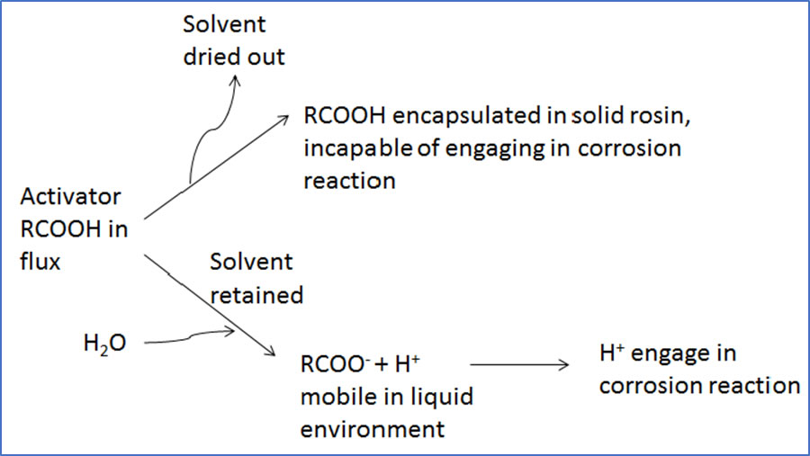
Figure 1: Flux activator under two different conditions [3]
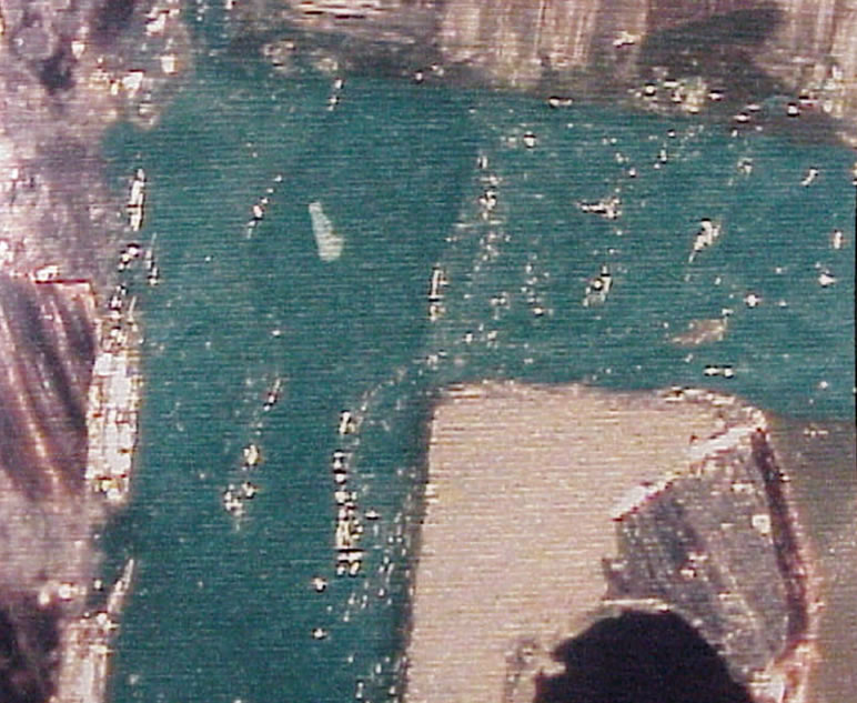
Figure 2: Tacky thick layer of flux under QFN component [1]
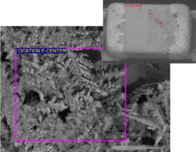
Figure 3: Dendrite formation under capacitor covered with electromagnetic shield having no holes [3]
No-Clean Flux Under Conformal Coatings
Conformal coatings are regularly utilized in the concluding stage of the manufacturing process to bolster the corrosion resistance of the PCBAs. The low cost, great moisture resistance and easy reparability makes acrylic coatings the favored choice among manufacturers.
Another reason for selecting acrylic coating is their use in critical applications. One case study [2] discusses the performance of acrylic conformal coating in the presence of no-clean solder flux. For testing purposes, two acrylic-coated substrates (FR-4 plain laminate and a SIR PCB) are used. The no-clean flux under consideration consists of 80-90% 2-propanol, 5-15% ethyl alcohol, and <2% carboxylic acid [2]. To understand the role of no-clean flux, three types of laminate and SIR surfaces are under consideration.
- Cleaned with Isopropyl Alcohol (IPA)
- Flux-contaminated
- Flux-contaminated and heated to 255oC
While the cleansed surface shows no flux residues, the laminate surface at room temperature contains greater quantity of flux residue compared to the laminate surface that was heated. Figure 4 and Figure 5 shows Scanning Electron Microscopic analysis of both surfaces. Figure 6 depicts similar results after exposing the surfaces to water (60oC). The contaminated and heated surfaces clearly show blisters.
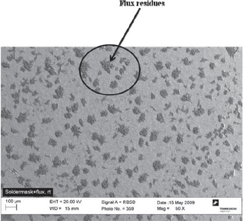
Figure 4: Flux residue on contaminated solder mask surface (room temperature) [2]
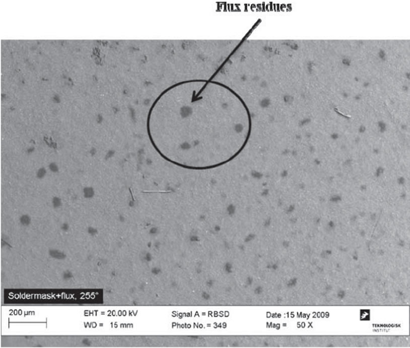
Figure 5: Flux residue on contaminated solder mask surface (heated to 255oC) [2]
Besides blisters, other defects like fish-eyes, pin-holes, and measles are sometimes observable.
The results in SIR test substrates are no different to those in FR-4 laminates. Owing to moisture permeation through the coating, contaminated and heated SIR substrates showed significant increase in leakage current as depicted in Figure 7. The degradation of coating and corrosion in SIR pattern was easily visible (images not shown here). The results clearly show that no-flux residue remnants are detrimental for conformal coatings under harsh environments. Researchers have identified the combinations of no-clean fluxes and conformal coatings that work well without initially cleaning the PCBA [4]; however, there are few cases that support leaving no-clean flux without ramifications.
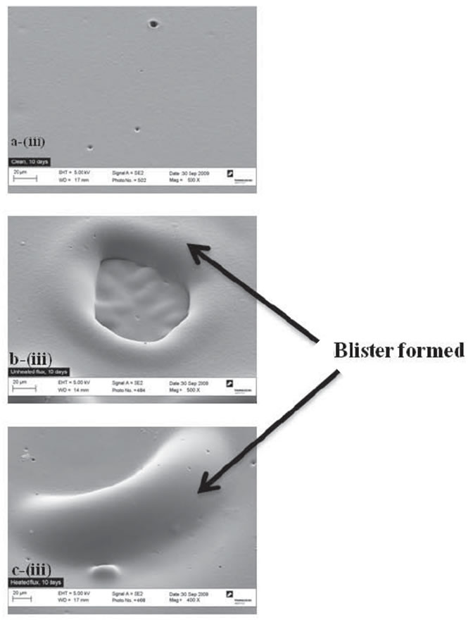
Figure 6: SEM analysis of all three surfaces after water exposure [2]
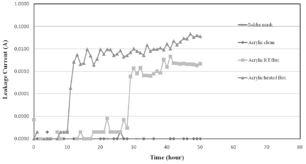
Figure 7: Leakage current across SIR PCB patterns [2]
9 Steps to Ensure Reliability with No Clean Flux
For a no-clean flux system to be risk free, there are some general guidelines for process engineers.
1. “No-clean” is a marketing term. Clean PCBs (at least mission critical ones) after wave-soldering and before conformal coating remains the best practice.
2. Apply sufficient flux for proper wetting during wave/selective soldering process.
3. Apply high temperatures for proper durations to render the flux benign.
4. Ensure availability of vent holes for flux fumes and solvent during the reflow process. The holes may be tape masked once flux residues become benign.
5. Avoid flux overspray and flux spread from hand soldering.
6. Subject the electronic assembly to rehydration before the system test, using non-condensing moisture at 40°C/90% RH, which can enhance the likelihood of detecting defects [5] that might otherwise be categorized as "no defect found."
7. To avoid a type 2 error (fault goes undetected) in SIR testing of no-clean flux, the recommended testing conditions are 40oC and 90% RH [1].
8. Occasionally, corrosive flux is discovered post-assembly. Cleaning is the optimal course, but in situations where cleaning is not viable, a post-bake procedure may be utilized [1].
9. For low standoff components, solvent-based cleaning may be more effective due to its lower surface tension compared to aqueous cleaners.
Chemtronics – the Cleaning AND Coating Experts
Chemtronics' products offer a distinctive advantage in the realm of electronics maintenance and protection, stemming from their unique expertise in both electronic cleaners and conformal coatings. This dual proficiency empowers customers with an integrated solution to ensure optimal performance and longevity of electronic components.
This comprehensive approach not only enhances operational efficiency but also extends the lifespan of electronics, reducing maintenance costs and downtime in various industries such as medical device manufacturing, aerospace, and automotive electronics.
We are available to help qualify new cleaning processes, evaluate current processes, or troubleshoot contamination issues. For more information or technical support, contact Chemtronics at [email protected] or 678-928-5845.
References
[1] P. Isaacs and T. Munson, "What makes no-clean flux residue benign?," in 2016 Pan Pacific Microelectronics Symposium, Big Island, HI, USA, 2016.
[2] U. Rathinavelu and P. M. R. A. Morten S. Jellesen, "Effect of No-Clean Flux Residues on the Performance of Acrylic Conformal Coating in Aggressive Environments," IEEE Transactions on Components, Packaging and Manufacturing Technology, vol. 2, no. 4, pp. 719-728, 2012.
[3] F. Chen and N.-C. Lee, "The risk and solution for no-clean flux not fully dried under component terminations," in 2015 16th International Conference on Electronic Packaging Technology (ICEPT), Changsha, China, 2015.
[4] T. O. Karl Seelig, Global Solder Solutions, [Online]. Available: https://aimsolder.com/technical-articles/conformal-coating-over-no-clean. [Accessed 27 08 2023].
[5] P. Isaacs, J. Bennett and T. Munson, "Evaluation of no-clean flux residues remaining after secondary process operations," in 2018 Pan Pacific Microelectronics Symposium (Pan Pacific), Big Island, HI, USA, 2018.
Haga una pregunta técnica
Manténgase actualizado sobre noticias, productos, videos y más de Chemtronics.
Productos relacionados